
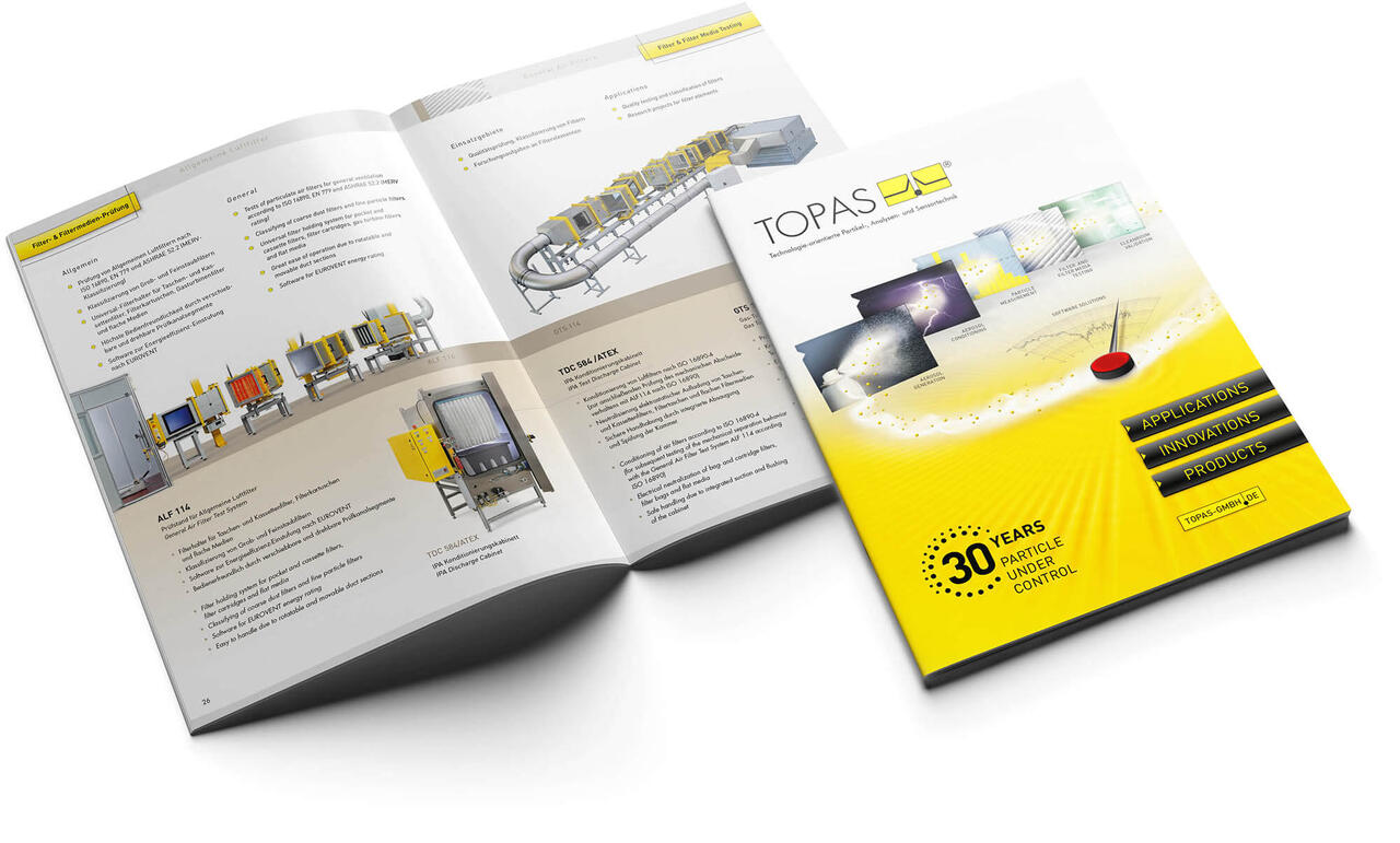
Unser Betätigungsfeld
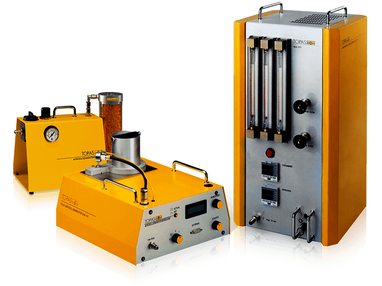
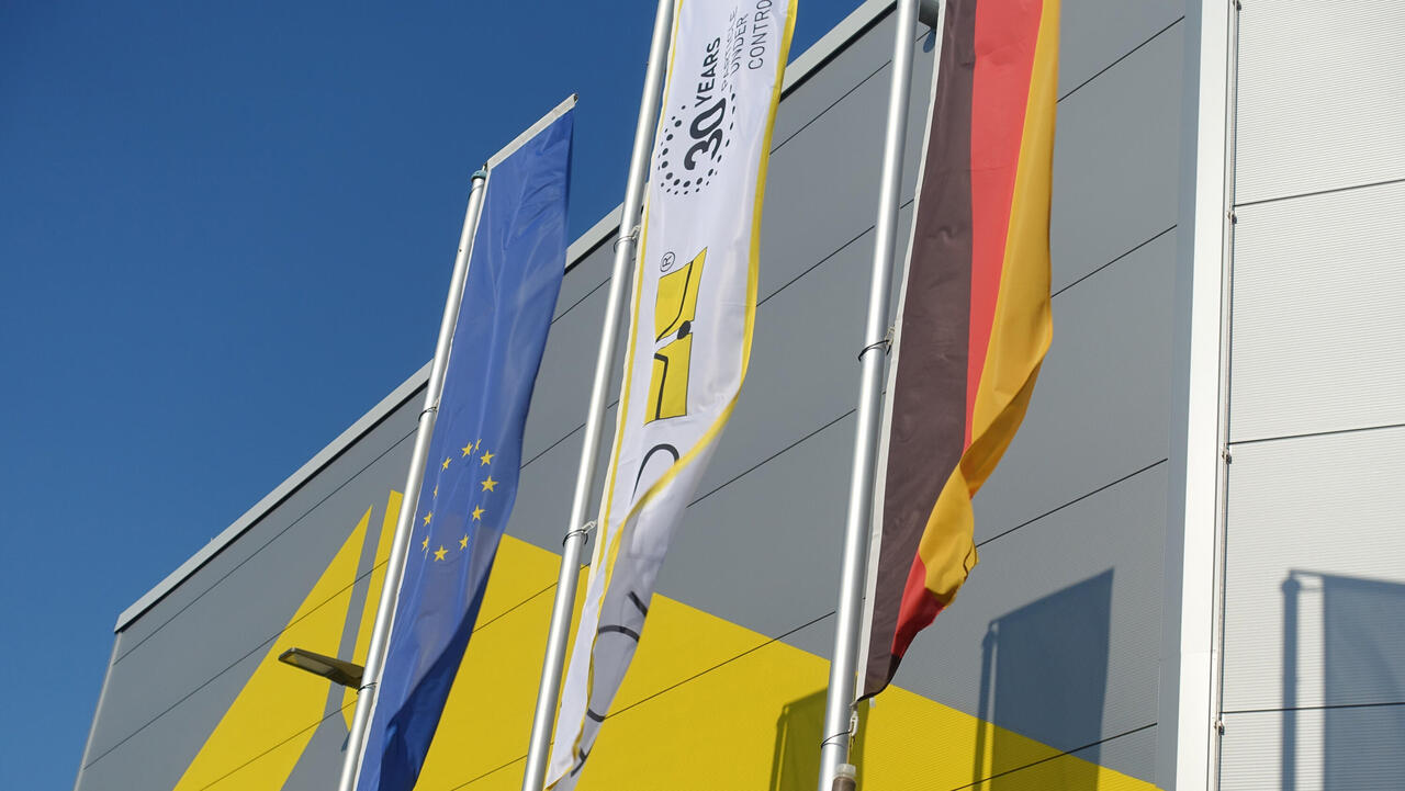
Seit über 30 Jahren werden unter dem Namen Topas technologieorientierte Partikel-, Analysen- und Sensorsysteme entwickelt, gestaltet und hergestellt. Mit ihnen können Prüf- und Referenzaerosole erzeugt, konditioniert und analysiert werden. Über 60 Seriengeräte und 20 Prüfsysteme unseres mittelständischen sächsischen Unternehmens sind darüber hinaus für die Klassifizierung und Testung von Filtern und Filtermedien seit Jahrzehnten in der weltweiten Industrie und Grundlagenforschung verbreitet und bewährt.
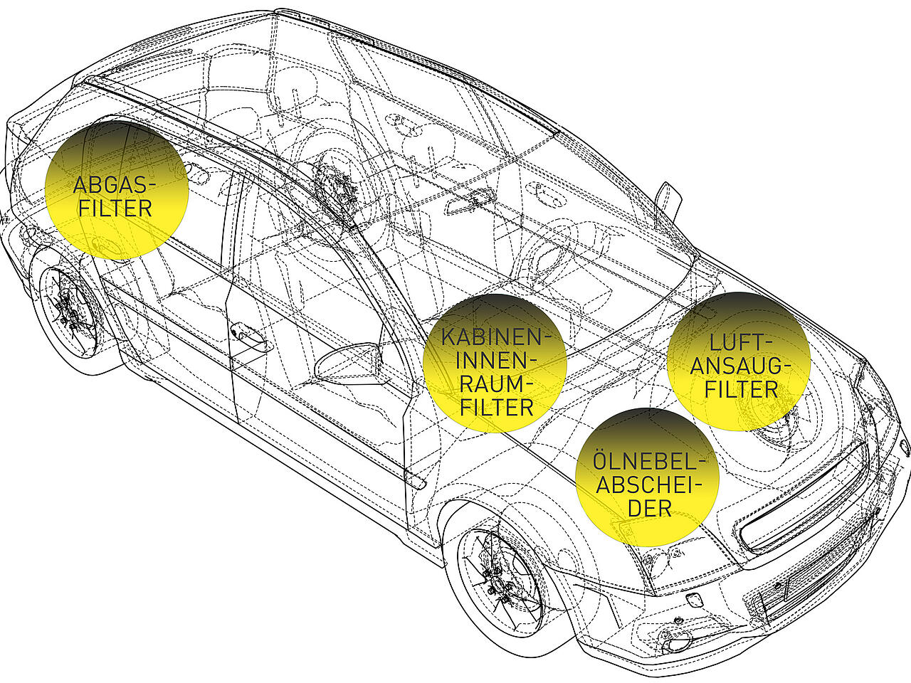
Anwendungsgebiete für unsere Produkte
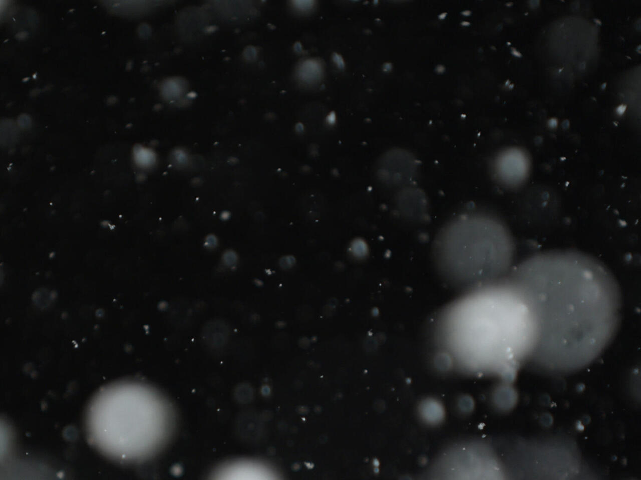
Von wegen nebulös: der neue CFG 291 Nebelgenerator bietet Reinraumexperten klare Vorteile
Reinraumdienstleister aufgepasst: der neue CFG 291 Nebelgenerator erzeugt gut sichtbaren, stehenden Nebel zur Visualisierung von Luftströmungen gemäß Normenreihe ISO 14644 oder entsprechend Richtlinie VDI 2083-3. Schnell, unkompliziert, praktisch und anwenderfreundlich punktet er mit einer Vielzahl von Vorteilen. Der impulsarme Nebeleintrag in die vorhandene Raumströmung mit einer speziellen Abströmsonde orientiert sich an den realen Testanforderungen unserer Kunden. Langwierige Unterbrechungen sind Vergangenheit dank leicht wechselbarer, handelsüblicher Akkus. Selbst die Verdampfer-Cartridge kann vor Ort selbständig ausgetauscht werden. Zur Erstabnahme sowie bei routinemäßigen Kontrollen von reinraumtechnischen Anlagen wird der CFG 291 mit unserem nichttoxischem Nebelfluid TopFog Regular und Light betrieben. Mit dem Nachfolger des beliebten CFG 290 sind Sie auf der richtigen Fährte: Finden Sie Leckagen in Übergangsräumen von Reinraumelementen, weisen Sie eine laminare Verdrängungsströmung nach oder visualisieren Sie das Überdruckniveau in Ihren eigenen oder den reinen Räumen Ihrer Kunden. Weitere Informationen erhalten Sie im Produktprospekt.

Aktuelles
Termine
Unternehmensvideo
Zertifizierung
Seit 1999 ist das Qualitätsmanagement der Topas GmbH erfolgreich nach DIN EN ISO 9001 zertifiziert.
Das BSFZ-Siegel wird exklusiv Unternehmen zur Verfügung gestellt, die Forschung und Entwicklung im Sinne des Forschungszulagengesetzes betreiben. Uns wurde es für die "Entwicklung eines neuartigen Verfahrens zur Signalauswertung und -verarbeitung für optische Aerosolspektrometer" verliehen.
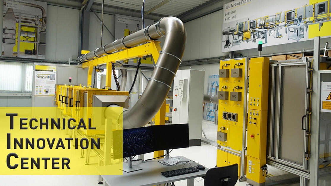
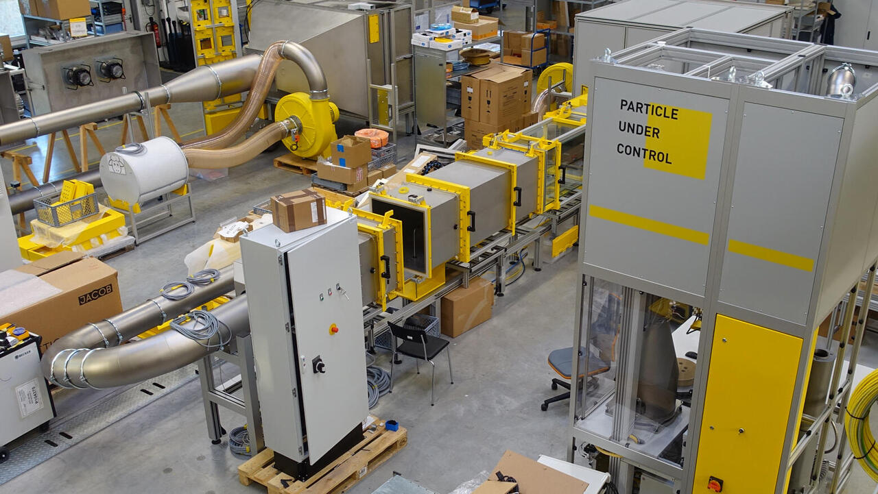
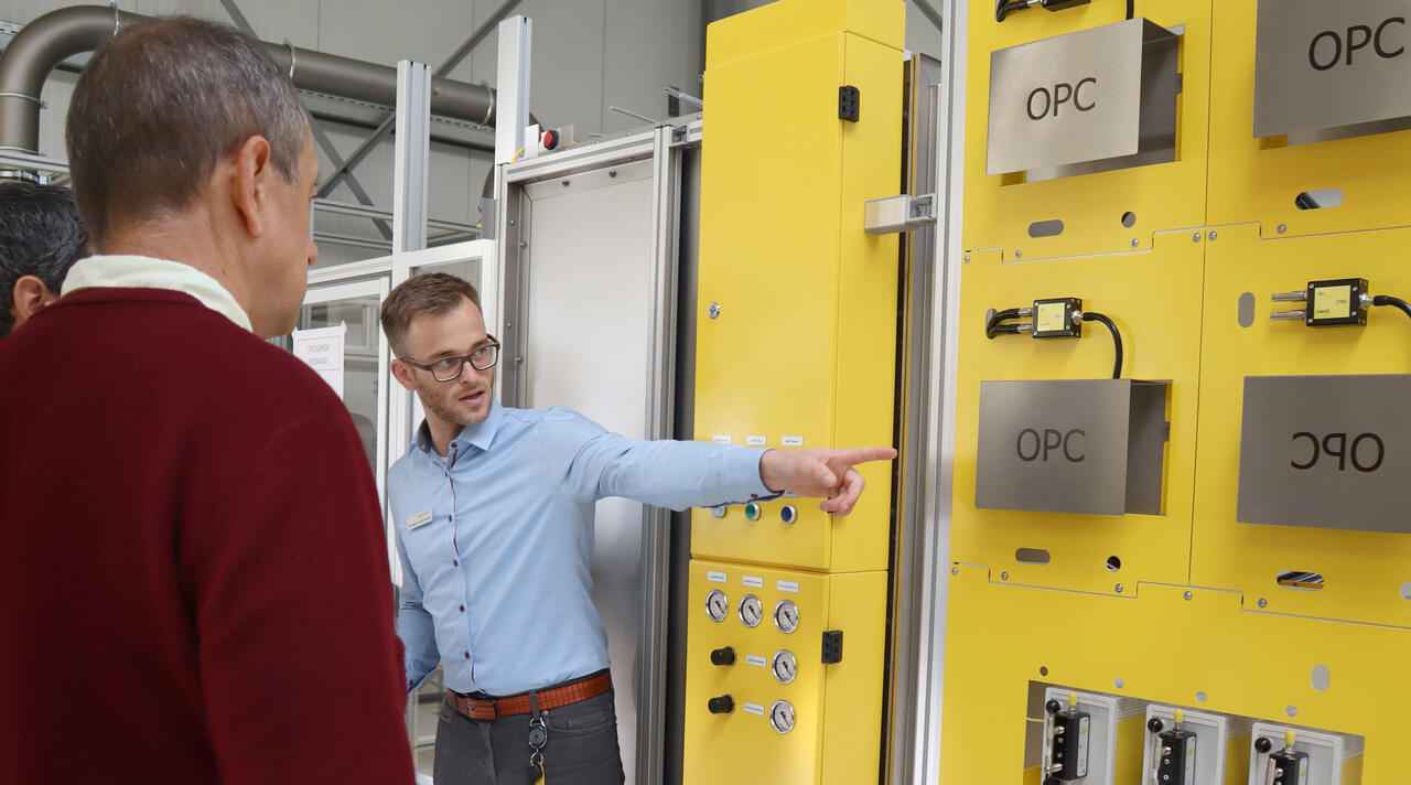
Beste Bedingungen für eigene Messungen in unseren Räumlichkeiten
Im TIC, unserem Technical Innovation Center, stehen Ihnen die Türen offen: Führen Sie Messungen an unseren Prüfständen durch und erfahren Sie mehr über die Leistungskennzahlen Ihres Produktes. Qualifizieren Sie Ihre Produkte auf diese Weise selbst. Darüber hinaus können auch Schulungen, z.B. für neue Bediener an diesen Systemen, durch erfahrene Topas-Ingenieure angeboten werden. Im kürzlich neu eröffneten Zuhause der Topas-Academy, Wirkort unserer Entwickler und Forscher, stehen Ihnen moderne Schulungsräume und Demonstrations- und Messtechnologie für Ihre Vorhaben zur Verfügung. Bitte sprechen Sie uns an oder lesen Sie mehr unter Technical Innovation Center & Topas-Academy!