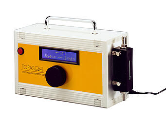
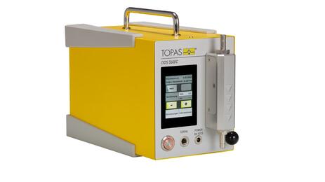
VDS 562 Dilution System
Variable Dilution System VDS 562 for variable adjustable, pressure drop compensated dilution of aerols at defined air flow rates
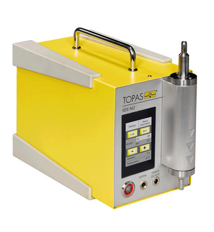
The Variable Dilution System VDS 562 was especially developed to lower concentration levels of highly concentrated aerosols to adequate concentration levels by one device, without external particle-free air supply and negligible pressure drop.
For optimal aerosol-analytical conditions, several measurement and test applications require a defined reduction of the particle number concentration (VDI 3491). Depending on the application, dilution factors between > 1 up to 1’000’000 can become necessary. In practise, especially the realisation of high dilution factors (> 1'000) is complicated (e.g.: cascading of dilution systems) and is accompanied either by a considerable pressure drop or by an excessive air consumption. The dilution factor of a VDS 562 can be varied within each operation range over approximately one decade. According to the customer’s requirements, one VDS 562 device can be calibrated for multiple flow rates from 28,3 l/min up to 100 l/min.
Standards
VDI 3491-6
VDI 2083
ISO 21501-3
download
product sheet VDS 562Benefits
- considerable high, infinitely variable dilution by one device (up to 1:100’000)
- to be calibrated at factory for multiple flow rates between 28,3 l/min – 100 l/min
- pressure drop compensation by implemented blower (active dilution)
- controlled set point dilution and possibility of remote-controlled adjustment
Applications
- reduction of high particle concentrations to analytically-suited concentration levels
- dilution of raw gas concentrations approval/validation of clean rooms (VDI 2083)
- avoidance of agglomeration (coagulation) in sampling lines for process monitoring
- validation of optical particle counters for clean room applications (ISO 21501-4)
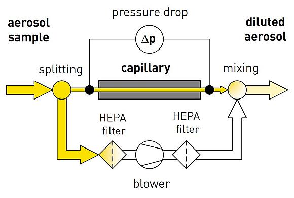
The principle of operation of the VDS 562 is based on the approved dilution principle used by Topas, where the inlet aerosol flow is split at first by a flow resistance (capillary).
After particle separation from the bypass, both the capillary flow and bypass flow are consolidated. This results in a reduced concentration at the outlet of the dilution system.
A controlled blower within the bypass compensates pressure drop and serves for automated readjustment of the flow rate to ensure a constant dilution over time.
| Parameter title | Unit | Value |
|---|---|---|
| purpose of conditioning | - | dilution of aerosols |
| sample condition, outlet | - | diluted aerosol |
| setting parameter | - | dilution factor |
| setting range | - | 12 ... 100'000 (range depending on type of capillary and flow rate, see product sheet) |
| setting resolution | - | 1 |
| setting method | - | manual, controlled |
| aerosol, volumetric flow rate | L/min | 28,3 ... 100 (calibration: 1 - standard, more - optional) |
| sample condition, inlet | - | non-diluted aerosol |
| power supply | - | 24 V DC, 1,3 A (including power supply pack for 110...240 V AC) |
| communication interface | - | manufacturer-specific (requires optional serial cable) |
| user interface | - | touch screen |
| power consumption | W | max. 35 |
| noise emission | dB(A) | max. 62 ± 3 |
| hose connector | mm | Ø 8 (28,3 L/min), Ø 13 (> 28,3 L/min) |
| environmental condition, max. counterpressure | kPa | ± 10 |
| dimensions (w × h × d) | mm | 130 × 200 × 300 |
| weight | kg | 3,4 |
- remover for capillary exchange and cleaning
- antistatic silicon tube (∅4,8 mm, ∅ 7,9 mm)
- serial cable to D-Sub-9 or USB
